


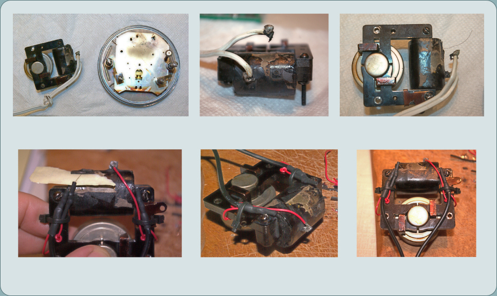
First Inspection:
Note poor consideration of wire strain relief
Tab broken off cardboard support. Cause of short circuit
Note the fine wire from the coil
Fine wire joined to ‘thin’ wire. Heat shrink tubing is used to cover all connections
Thin wire is knotted before and after iron bracket holes.
All wires are secured with zip ties

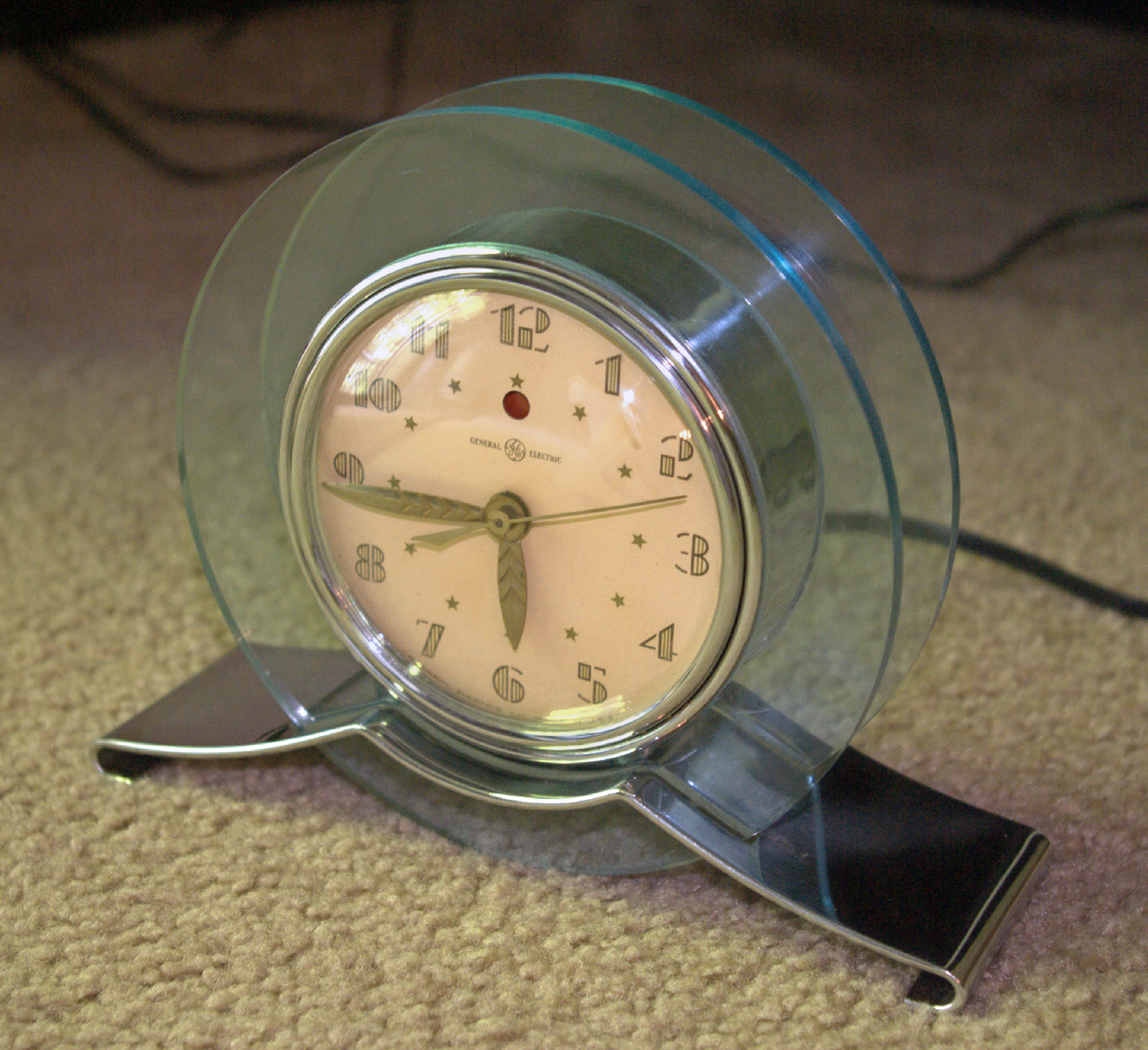
Vintage 1940’s Electric Clock Repair
General Electric “The Rapture” Telechron


60 cycles per second X 60 seconds = 3,600 revolutions per minute
Front
Recently this clock was plugged in after years of storage. Surprisingly, a sharp white spark and noise emitted from inside. This short circuit shut off the power from the breaker box. Thankfully no one was injured or property damaged.
The Rapture line of clocks were generally made from the late 1930’s until 1942 when war efforts required the attention of companies like General Electric. These clocks operate on the regular United States electrical line of 120 volts alternating current @ 60 Hertz. Interesting to me is that the rotor (motorized component that turns the drive gear) is set to turn at precisely 3.6 Revolutions Per Minute. At first I thought this to be an odd number to set a motor to but I now see why this motor is calibrated to run at precisely the correct rate because it is governed by the 60 Hertz rate of the power grid.
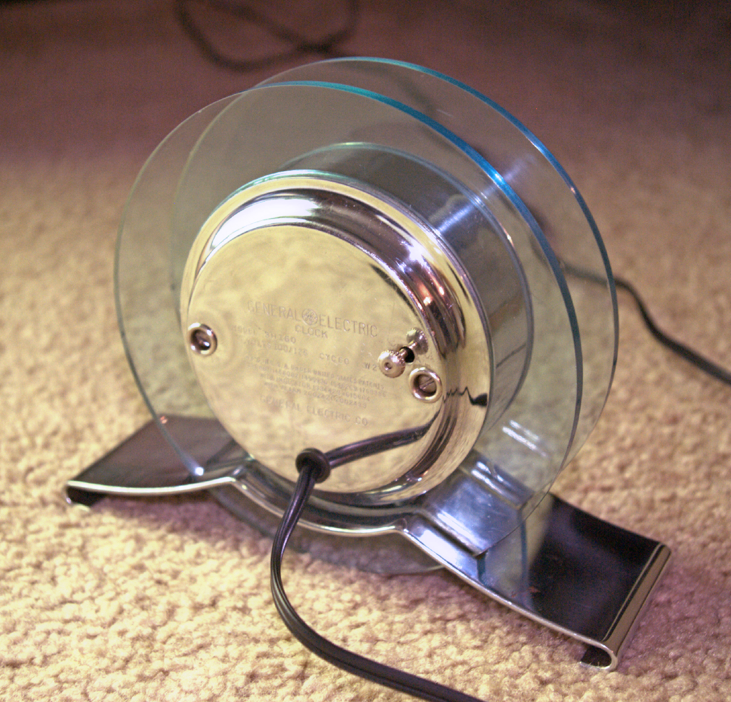
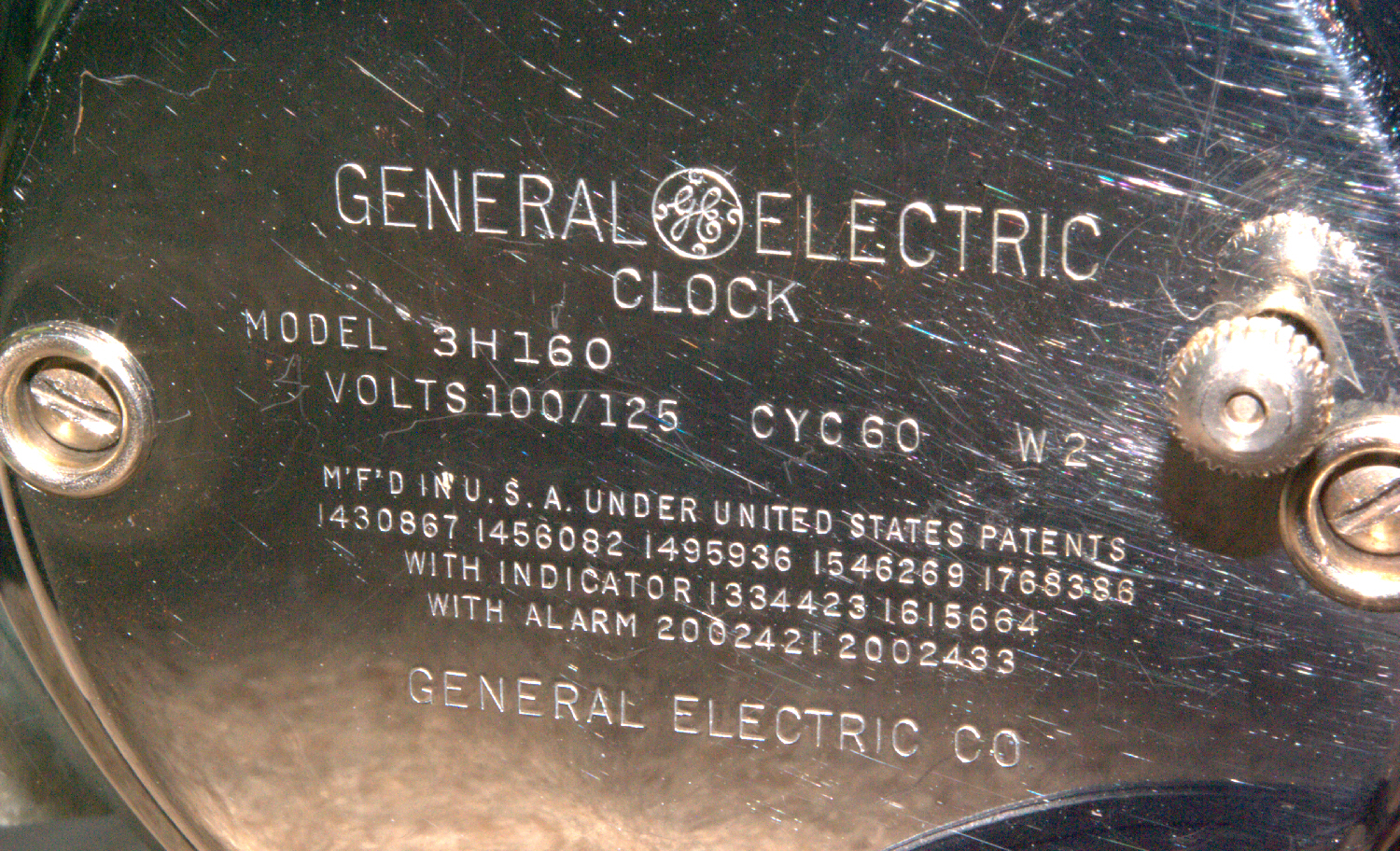
Back
Model: 3H160
3,600 revolutions
1000:1 Gear Reduction Ratio
= 3.6 revolutions per minute
The cause of the short was because one of the wiring tabs had broken off of it’s cardboard base that is wrapped around the electromagnetic coil. The original wire had been replaced many years ago (the white appliance wire) with poor consideration for normal cord movement/agitations. This eventually let to the tab breaking off and touching the other wire.
To make the repair I needed to somehow connect to the fine wire from the coil and keep it safe from agitation strain. The coil wire is only about the thickness of a human hair. I decided to first use a thinner wire to connect to the coil wire and secure it to the iron bracket. At the other end of the thinner wire I attached a new appliance wire. I decided to make all wiring secure by using a zip tie to the iron bracket. This approach should stop all strain from reaching the delicate coil connections.
An interesting aspect to note is that the rotor is easily removable and operates on the electromagnetic inductance transmitted from the coil through the iron bracket. The resistance of the coil measures to be around 749 Ohms.
Also featured on many of these clocks is the red indicator “eye”. This was to signal to a person that electrical service had been interrupted and so the indicated time should be placed in question. Early electrical service was more prone to blackouts and people couldn’t simply turn on a television or check the internet for the time. This was an era where a lot of clocks were still spring or weight driven. The indicator on this clock works fine and the rest of the clock is functioning perfectly after reassembly and some oil to the moving gear pivots.