

PROBLEM: The Klipsch ProMedia 2.1 speaker system is a very nice unit for enjoying music and movies. It has nice rich sound with impressive bass. It’s even certified with the THX movie audio label to meet high sound quality standards.
We had our unit for about 9 years and suddenly the unit would not show any signs of life. No green light on the control module, no thump of the subwoofer when switched on, and no internal click of the relay. What do you mean don’t panic.....a new set only cost $200 and just to have the thing serviced starts at $75! Since I had just finished reading a book about electronics I decided to give this repair my best attempt and thankfully it worked.
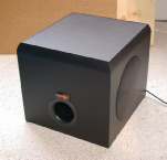
The subwoofer of the
Klipsch ProMedia 2.1
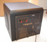
Panel layout

Klipsch ProMedia 2.1
Speaker System Repair
Back Aluminum Panel
(heat dissipater)
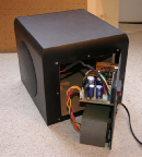
Opening Panel
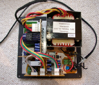
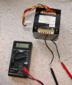
Testing main transformer
primary wiring
SOLUTION: A search for the transformer revealed that the transformer is no longer available for purchase. What you should do is then find a broken Klipsch system for sale on eBay that matches your system and swap out the transformer. Please use the above table to see that your transformer is performing properly if you are having a power problem. If you look at Dale Thompson’s schematic it describes a transformer that provides 80 Volts AC center tapped and 40 Volts AC center tapped to the system. If this certain transformer is not available you (after trying the eBay route) you can use different ones as long as it has they have the same exact values and are also center tapped (bipolar).
Installation of the new transformer went pretty with some soldering and heat shrink tubing and I was delighted when first switching it on I could hear all the usual signs of life. But OH NO!!!!!! I was missing sound from the right sided speaker!!!! See page 2 from my Klipsch Home page.
I found an excellent webpage posted by Dale Thompson that provides many electronic schematics and descriptions to explain the operation of the 2.1 ProMedia system.
The first step was to check that the main fuse was not blown. It is easily accessible next to the On/Off switch. The fuse appeared intact to the eye and also checked fine when testing with a digital multimeter (DMM). Next I removed all screws to open the access panel. I carefully inspected the circuit boards for any signs of extreme heat and damaged components. Everything looked ok, darn.
Starting with the simple issues first I used the DMM to check issues like a broken power cable or a faulty on/off switch. Nope. I checked for voltage across the primary wires heading into the main transformer and it was fine at 120VAC. After studying the schematic for the main power supply I noticed that the next step was to test the secondary transformer wires that provide lower voltage both in positive and negative relation. These voltages should be +/- 80 Volts and +/- 40 Volts. This is know as a bipolar power source. Upon testing for energy I realized that there was nothing there! I then realized that the top of the transformer has a label stating “Built-In Thermal Fuse”. This means that if for any reason there’s a high heat situation inside the transformer it will blow the fuse and effectively “kill” itself in order to keep things safe. This is a one time only fuse and once it’s blown that’s it. There’s no reasonable way to open up the transformer to get to it (I tried). There could have been a number of reasons why the meltdown started in the first place and it just isn’t safe to reconsider reusing this transformer.
Upon realizing that there was a problem with the transformer I decided to completely remove the transformer from the system and run a check to test the primary and secondary wires for resistance, again with the DMM. Ah-Ha! Infinite resistance was indicated on the primary wires which meant that the fuse had indeed blown. One note to add: When measuring wires with the DMM probes make sure that your fingers are not touching the probes at the same time. I discovered that your human body will actually show a resistance of about 600K to 1.5 Megaohms when you do this. At first I thought the transformer was ok, but after making sure that my fingers were away from the metal probes it confirmed that there was surely a break inside the primary circuit.

An excellent book to
learn about electronics
“Teach Yourself
Electricity and
Electronics”
by Stan Gibilisco
Secondary
wiring plug
Resistance Values of New Transformer
Primary wires = 2.8 ohms
Secondary
Wires 1 to 2 = 1.2ohms, Wires 1 or 2 to 3 = .8 ohms
Wires 4 to 5 = .8 ohms, Wires 4 or 5 to 3 = .6 ohms
Secondary Voltages of New Transformer
Wires 1 to 2 = 75.8 VAC, Wires 1 or 2 to 3 = 37.7 VAC
Wires 4 to 5 = 40.2 VAC, Wires 4 or 5 to 3 = 19.9VAC


SYSTEM IS FULLY FUCTIONAL AGAIN

ISSUE: #1 Problem
Failure of main power transformer
REACTION: After doing a good amount of searching on the web about the ProMedia system I found a lot of other owners have similar and sometimes worse problems with their units such as burnt out resistors, capacitors, transistors or issues with the control module. Some people note that their units get quite hot on the back aluminum access panel and I know from opening the unit that the power amplifier transistors are coupled to this panel to keep them cool. For any transistors that I did happen to unbolt from the panel I was sure to reapply some thermal compound paste to keep them coupled.
(Model #: V2.1-02492567 CSA #: 205697)

Klipsch 2.1 ProMedia Schematics - Credit Dale Thompson
Block Diagram
High Frequency Amplifier
Control Pod
Input/Output
Power Supply
DIN Plug Diagram
Interconnect Diagram
Low Frequency Amplifier

Be sure to see Dale Thompson’s website for up to date schematic diagrams including the 4.1 and 5.1 systems!
CLICK HERE

