


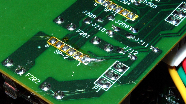
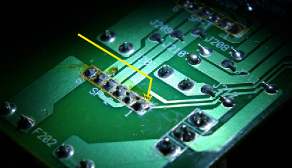
Repair made with wire strand and solder
Repair made with wire strand and solder


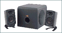
PROBLEM: The second problem that strangely occurred during the time of the transformer failure was surprisingly simple. The right sided speaker had gone dead.


An excellent book to
learn about electronics
“Teach Yourself
Electricity and
Electronics”
by Stan Gibilisco


ISSUE: #2 Problem
Corrosion of circuit board tracing. Located and fixed.
REACTION: To test that the speaker and wire were o.k. I simply moved the wire connections to the left side and it worked fine.
I knew that power was getting to the right side because as I would reconnect the wires I could hear a crackling/static sound. This got me to thinking that since the power was o.k., there must be a issue with the audio signal not getting through. I even thought that the transformer failure had caused a power surge to ruin one of the integrated circuit (IC) chips.
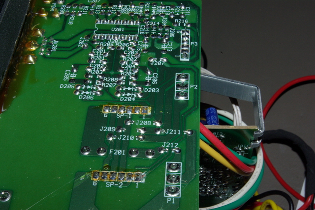
After carefully looking at all the schematics provided by Dale Thompson’s website I determined that some possible components for signal failure were one of the IC chips (item U201 on the board (TL074)) or some of the power amplifier transistors (items Q9 & Q10 on the board (TIP41C and TIP42C)). To prepare myself I put an order into Digikey for the parts since it only cost about $7 total but funny thing is that in the end I didn’t need any of them.
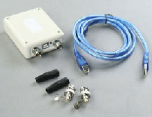
What really helped me find the problem was to use an inexpensive oscilloscope I had purchased a few months before. These digital oscilloscopes only cost about $30 and run off a USB connection to your computer with the included program. I should note that the unit I use only sees the positive side of AC signals. To check the negative side you need to switch the leads around. More nicer units can see both positive and negative voltages at the same time and some can even work independently with their own LCD screen eliminating the need of a computer. All depends on how much you would like to buy. My scope will see voltages up to 5 volts and frequencies up to 3 Kilo Hertz. For voltages higher than 5 volts you need to use an attenuator or a voltage divider. This is a set of resistors that reduce the large voltage to a smaller one. I strongly recommend that you get yourself one of these scopes to learn and diagnose the areas on your system that are working.
I used the probe ends of my DMM to work with the oscilloscope. The first connection I made with the scope was to connect one of the leads to ground, look to the schematic to be sure of where you can do this. This is a process that involves turning the sound system on so be very very careful of all surfaces because you could get shocked!
AGAIN! BE CAREFUL WHEN WORKING AROUND A DEVICE WHEN IT’S PLUGGED IN AND RUNNING!!!!!
Next came the very careful probing around with the other lead to see where audio signals were showing up and where they were not. I had to unplug all speakers and turn the volume up a good amount in order to see the signals register on the computer program. I first tested the main IC chip that processes audio (NOT THE POWER POINTS!!). All fine. I even probed the control pod DIN pins and signals were good there too. I then tested the pins for both the SP-2 and SP-1 points. What’s nice about this is that I had the two areas to make comparisons.
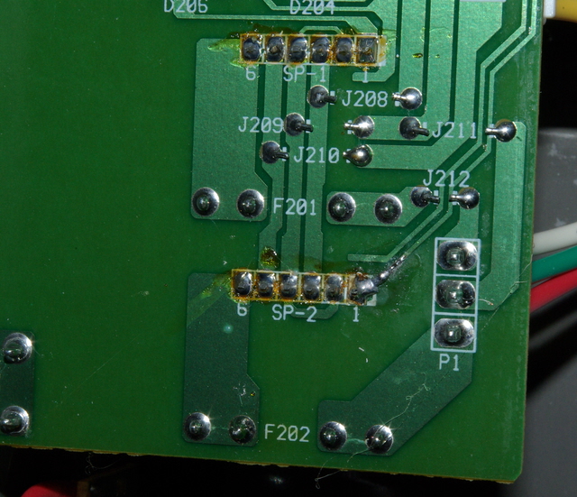
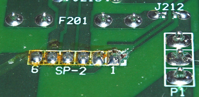
Pin #1 on the SP-2 collection wasn’t showing signal. But when I followed the copper tracing line “upstream” to the next component it did have signal. So I knew that the problem existing between two points and that revealed a corossion spot right next to the #1 pin. How simple and yet how sneaky!! It was just a fracture line break that caused all this problem.
The $30 digital oscilloscope I have
Tested the TL074 chip for signals:
GOOD
No signal was getting here
Corrosion on tracing before solder point
SOLUTION: When I found the corrosion I cleaned away a bit more of the trace line and tested it or signal. It was good.
I simply took a single strand of wire and used it to make a solder bridge between the #1 pin and the trace line. Problem fixed!
If you should need help with your system feel free to write me an email and I will see if I can help. Best of luck to you!
Problem
Found!
Left channel Input/Output
Right channel Input/Output
Klipsch ProMedia 2.1
Speaker System Repair
SYSTEM IS FULLY FUCTIONAL AGAIN

Be sure to see Dale Thompson’s website for up to date schematic diagrams including the 4.1 and 5.1 systems!
CLICK HERE